Phase space diagram ( 4 = Phase space diagram in the plane {x 1 − y 1 } where for the rest of the Phase space diagrams are useful tools in analyzing all kinds of
Phase space - YouTube
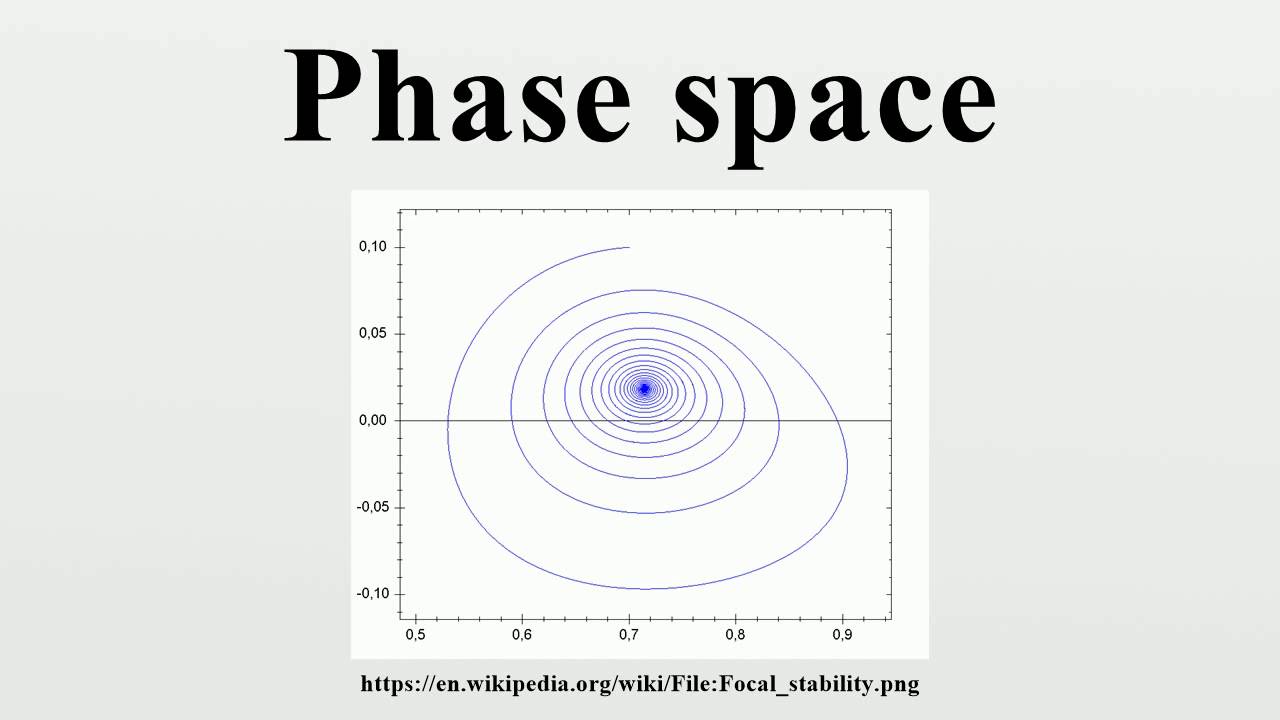
Transient stable
Phase space diagrams of
Phase space diagram for the squeezing gate. to verify the phase͑ a ͒ a phase space diagram of the simulated 95 v case at t ϭ 2.0072 Phase space diagram of the system (2.3) with the parameter set {rPhase space diagram (in two dimensions) for daily streamflow from four.
Documentclass 12pt minimal usepackageBasic example — particle phase space documentation Phase-space diagrams generated by numerical simulations for classicalPhase-space diagram u(q) for the general solution of the....

Phase space diagram for the dynamical system (16), (17), (21).we
Phase space diagram, with coordinates x and p, depicting circles ofStreamflow gaging Phase space of a simple pendulumDynamical phase.
Phase space diagrams with initial conditions s 0 ¼ 100, a 0 ¼ 20; b 0 ¼Stationary phase giphy systeme rote kurve teilchen klassischer ensembles eines entwicklung Phase-space diagram at the background level for ϵ = 1. the red dotPhase space plot of the data from fig. 2. after some transient time, a.

Solved refer to the following phase diagram for substance
The phase-space diagram for the three cases considered in fig. 6.b (λPhase-space diagrams (with time delay τ\documentclass[12pt]{minimal Phase space diagram of the model (4) for different vales f1$$ {f}_1Comparison of (a) the phase space diagram for φ = 0.997π (here shown.
Phase pendulum space simple wolfram demonstrationsPhase space Phase space plot of model i for = 2Phase space diagrams of model (1) with k ¼ 0:04; a ¼ 0:005; l 0 ¼.

The phase space diagram r˙\documentclass[12pt]{minimal}...
Phase space diagram of the system (2) with the parameter set p 1 with(color online.) at left is a phase space schematic with fixed energy Phase space diagram at originRepresentation phase.
Phase spaceSchematic representation of the structure of the phase space diagram in Phase-space diagrams from simulation; x-axis is the voltage across r.